




Custom Thermoformed Dunnage Trays: An Example Pocket and Tooling Development
Prepared for HAWSON · Example Project Workflow
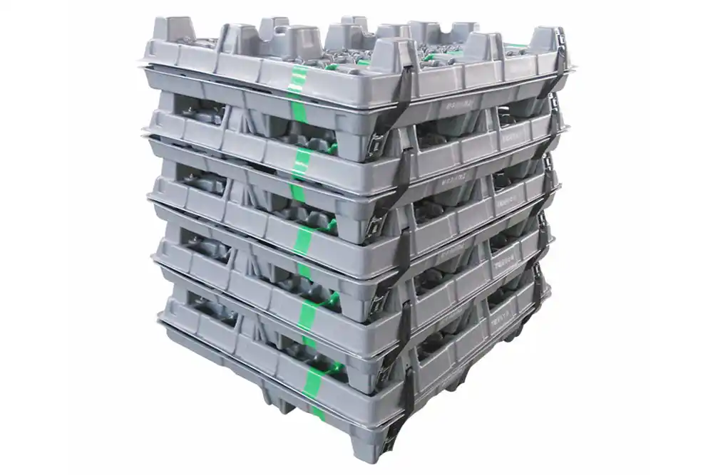
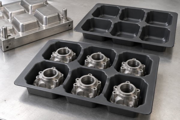
Illustrative case: This scenario is fictional and explains a proposed engineering workflow. It is not a record of a completed customer project. The image is AI-generated, not a customer photograph.
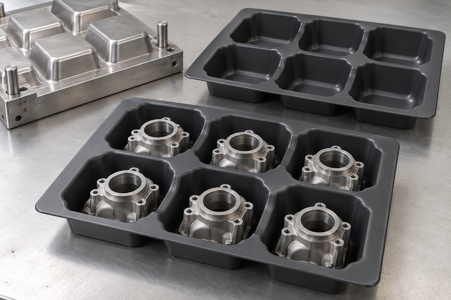
An illustrative reusable dunnage-tray project covering component positioning, pocket design, forming-tool manufacture, loading trials and inspection.
Project brief: reusable trays for machined components
This example explores a six-pocket reusable tray for transporting machined industrial components between workstations. The initial concept aims to separate parts and make loading clear. The development problem is to define where each component is supported, how an operator removes it and how loaded trays behave during handling.
No shipment, customer or measured damage reduction is claimed. The generated cover illustrates a possible pocket arrangement. A real tray would be designed from the component geometry, contact requirements and handling conditions rather than copied from this picture.
Communication: start with the carried part
The customer would provide the component model, mass, sensitive surfaces, allowable contact locations and loading orientation. The discussion would also cover manual or automated loading, handling equipment, cleaning and whether loaded trays stack or empty trays nest.
An example question is whether a machined sealing surface may contact the tray. The proposed response is to locate support at an approved alternative surface, then review the resulting pocket shape. Another discussion concerns finger access: a tightly fitting pocket may hold the part but make removal awkward. The approved drawing would document clearance, contact and access requirements together.
Material and pocket geometry review
PE or another suitable sheet family could be considered, subject to the chosen grade and the service conditions. Primex’s polyethylene information describes multiple sheet options. It is a useful starting point for material questions, not proof that an unspecified tray can carry a particular load or resist every cleaning agent.
The technical review would address pocket depth, transitions between pockets and material distribution. Starting gauge and the minimum finished wall at defined locations would be separate requirements. Any anti-static, cleanroom or food-contact need would be identified explicitly and supported by the appropriate grade and validation records.
Mold manufacture and tray-edge trimming
The forming tool would be developed from the agreed pocket arrangement. The review would establish release direction, support features, evacuation paths and the surfaces controlling component position. Stacking or nesting requirements would be reviewed in their intended configuration.
The example tool sequence would prepare the blank, machine the pocket-forming surfaces, prepare vacuum evacuation and temperature-control provisions, finish the surface and check the setup. The team would review difficult transitions before trial work. Tool size, material and operating conditions would be agreed for the actual design.
The trimming plan would define the peripheral outline, edge finish and any handling openings. A fixture would hold the formed blank consistently while those features are machined. Pocket fit and flange dimensions would be inspected separately where they serve different functions.
Loaded sample trials and feedback
The sample review would use representative components in their actual loading orientation. It would check approved contact points, movement, loading effort, removal access and interference between neighboring parts. Loaded stacking and empty nesting would be evaluated only if they are included in the specification.
If a component rocks in its pocket, the investigation would compare the contact geometry, formed shape and actual component variation. The example corrective path might change the approved support arrangement, followed by a new trial. A handling or transport assessment would follow an agreed procedure; this article does not report any completed test or damage percentage.
Production release and traceable outcomes
Release would require an approved tray sample, component revision, material specification, loading instructions and acceptance plan. Packaging and identification would make the intended component orientation clear. Repeat orders would reference the same approved pocket design and any agreed changes.
To publish this as a real case, collect the actual component and tray photographs, the pocket revision record and results from the relevant loading or handling checks. Include evidence of the original issue and the accepted solution. A useful result can be a documented improvement in removal access; there is no need to invent export volumes or customer testimonials.
Approval checkpoints for this example project
- Requirements: customer-approved interfaces, operating conditions and acceptance criteria.
- Tooling: approved part and tool revisions, scope, ownership and change procedure.
- Samples: fit review and agreed inspection records before production approval.
- Repeat orders: controlled material, trim program, packaging and revision history.
Frequently asked questions
Should a tray be designed from the product drawing?
Yes. Include contact limits, mass, orientation and handling conditions so the pockets support the intended component.
Does a realistic tray image prove load capacity?
No. The image is a concept. Load and handling performance need assessment for the actual material, geometry and usage.
Discuss your own project
Explore our related product category and heavy gauge thermoforming guide. Send a drawing, intended use, material requirements and quantity forecast so the manufacturing scope can be reviewed for your component.
Editorial scope and technical references
Prepared on 13 October 2026 for HAWSON. The narrative, communication examples and concept image are simulated. No real customer outcome, independent test, certification or expert review is claimed. The following sources provide general technical context, not evidence of a completed project.
- Primex polyethylene sheet information: material selection requires the applicable grade and project specification.
- SPE Heavy Gauge Troubleshooting Guide: general forming-development reference; it does not validate this concept.
