



Custom ABS Machine Covers: An Example from Drawing Review to Mold Trials
Prepared for HAWSON · Example Project Workflow
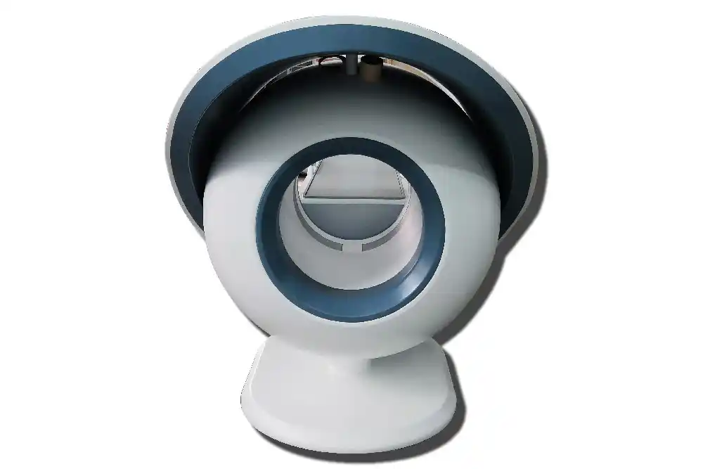
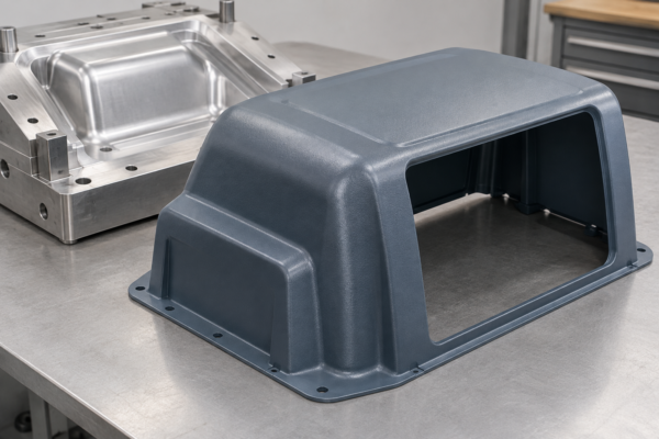
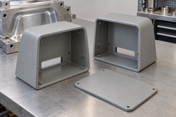
Illustrative case: This scenario is fictional and explains a proposed engineering workflow. It is not a record of a completed customer project. The image is AI-generated, not a customer photograph.
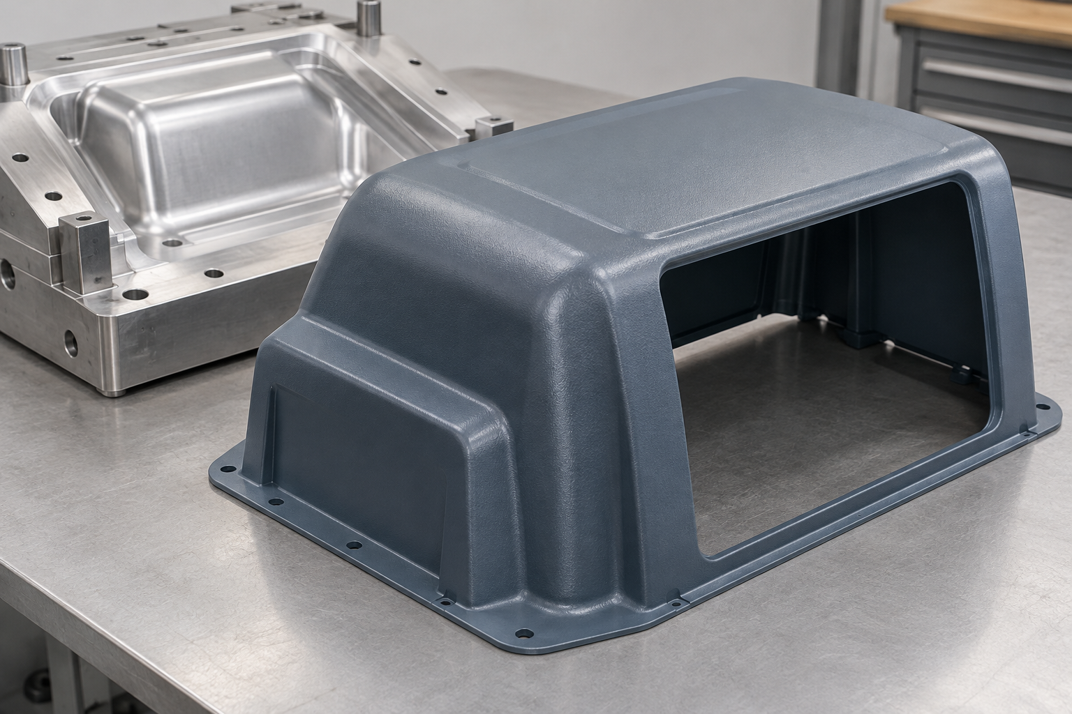
An illustrative ABS machine-cover project showing service-access communication, tooling manufacture, CNC trimming and sample approval records.
Project brief: an industrial equipment cover
This example develops an open-back cover for industrial equipment, with a large service opening and a peripheral mounting flange. The proposed blue-gray appearance is secondary to assembly fit and maintenance access. The central problem is to convert a broad exterior model into a cover that can be installed and removed without conflicting with the equipment.
The article describes a simulated workflow, not a completed HAWSON order. The illustrated cover is a concept. Its geometry, material and protective function would require review against the actual machine.
Communication: map installation and maintenance tasks
The customer would supply the frame, surrounding-component geometry and a description of routine service tasks. The development discussion would identify where tools and hands need access, whether the cover must lift vertically, and which fasteners should remain accessible.
An example design issue is a service opening that looks large enough but leaves insufficient space for a connector to pass through. The review would compare the connector envelope with the opening and maintenance procedure. The proposed resolution would enlarge or relocate the opening, subject to review of the remaining cover geometry. Purchasing and engineering would approve the same drawing revision.
ABS specification and functional boundaries
ABS sheet may be a candidate when a rigid exterior and an agreed surface finish are needed. Primex’s general ABS information supports discussing sheet options; a particular material still needs confirmation against heat, oils, cleaning agents and the machine environment.
The cover should not automatically be described as a safety guard. If protection against mechanical hazards is required, the customer must specify the applicable performance and validation scope. A visually solid plastic enclosure alone does not establish that function. The proposed wall requirements would identify mounting areas and regions needing particular stiffness.
Mold design and manufacturing sequence
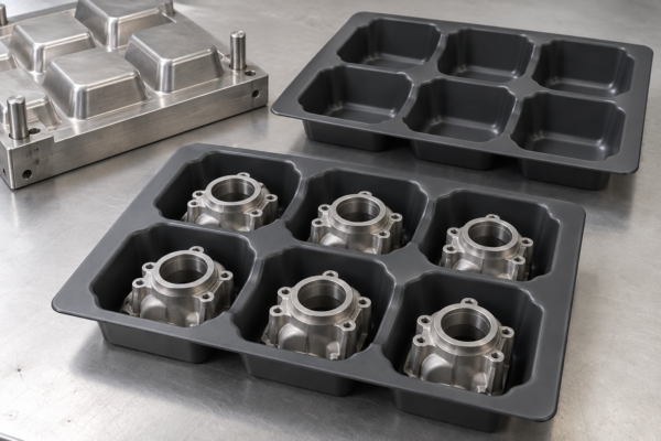
Tool design would begin with release direction and the chosen controlled face. The team would review radii, the service-opening region and material distribution before approving the tool model. The mold would produce the shell blank; the final opening and hole pattern would be covered by the trimming plan.
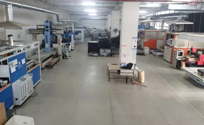
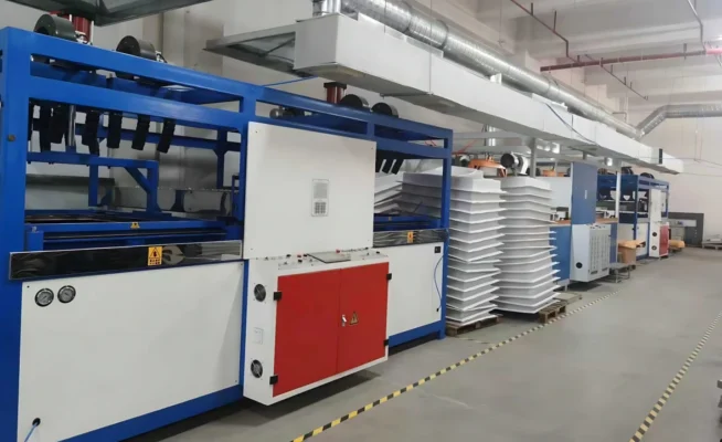
The example manufacturing sequence is preparation of the blank, CNC machining of the forming surface, development of vacuum evacuation and temperature-control provisions, finishing and setup verification. Actual tool materials and operating conditions would be agreed by the manufacturer for the project.
The trim fixture would support the cover in a repeatable orientation. Before trials, the drawing would define which mounting relationships are critical, the intended datum system and how inspection will be carried out. Tool approval would include these interfaces, rather than only a review of the external silhouette.
Trial communication and sample changes
Initial samples would be checked on the equipment frame. The review would confirm flange seating, fastener access, opening location and removal path. Surface acceptance would address the visible face, edge finish and any required texture.
If a flange does not seat consistently, the investigation would separate formed-shape variation from fixture support and frame alignment. The hypothetical corrective path would be selected only after checking those contributors. The next trial would keep a record of the tool or trim changes so the reason for the revision remains clear. The example does not claim a measured reduction in deformation.
Production release and useful project records
The release package would contain the approved component drawing, material specification, trim revision, acceptance criteria and packaging instructions. Where separate inserts or brackets are required, their attachment and inspection would be included in the scope. The image is not evidence of those operations.
For a genuine case article, use actual mold photographs, a documented sample change and final assembly evidence. Include the original problem and the verified result, with customer permission where needed. A real outcome may be a confirmed service-clearance issue resolved by a drawing revision; it does not need an invented percentage improvement.
Approval checkpoints for this example project
- Requirements: customer-approved interfaces, operating conditions and acceptance criteria.
- Tooling: approved part and tool revisions, scope, ownership and change procedure.
- Samples: fit review and agreed inspection records before production approval.
- Repeat orders: controlled material, trim program, packaging and revision history.
Frequently asked questions
Can a formed shell include a large service opening?
An opening can be incorporated into the project scope, often through trimming. Its location and effect on fit and stiffness require review.
Is a machine cover automatically a safety guard?
No. Safety functions and validation must be specified separately for the intended equipment.
Discuss your own project
Explore our related product category and heavy gauge thermoforming guide. Send a drawing, intended use, material requirements and quantity forecast so the manufacturing scope can be reviewed for your component.
Editorial scope and technical references
Prepared on 13 October 2026 for HAWSON. The narrative, communication examples and concept image are simulated. No real customer outcome, independent test, certification or expert review is claimed. The following sources provide general technical context, not evidence of a completed project.
- Primex ABS sheet information: material selection requires the applicable grade and project specification.
- SPE Heavy Gauge Troubleshooting Guide: general forming-development reference; it does not validate this concept.
